The circuit described below provides a simple speed control that will work with the kinds of brushless fans used to cool modern CPUs. These fans are small, low power, and readily available from computer shops. This design has a number of advantages over running the fan continuously at its rated voltage, or using other methods of speed control:
| Number | Description | Circuit Ref. |
|---|---|---|
| 1 | LM358 Dual op-amp | IC1 |
| 1 | BC441 | TR1 |
| 1 | 1N4001 | D1 |
| 1 | 330R 1/4w | R6 |
| 1 | 10k 1/4w | R3 |
| 4 | 47k 1/4w | R1, R2, R4, R5 |
| 1 | 47k Lin potentiometer | VR1 |
| 1 | 100nF Polycarbonate | C1 |
| 1 | 470nF 16v Electrolytic | C2 |
A 12v brushless fan will also be needed. The one I used was 4cm square, and rated at 160mA. Similar fans can be bought new from electronics suppliers either on their own or attached to heat sinks as CPU coolers, from surplus supplies, or salvaged from old equipment.
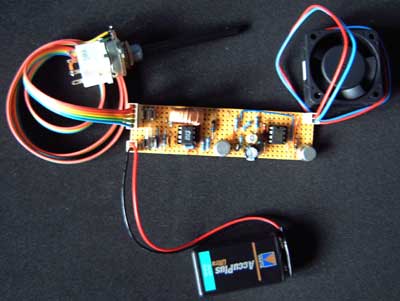
The prototype (see below) was built on strip board, and presents no special construction problems. There is no setup required. VR1 an either be a small preset if a fixed speed is required, or a regular potentiometer if the speed needs to be adjusted. In the latter case, a switched version may be convenient.
For some of the travel of VR1 the fan will not spin at all. The circuit is drawing very little current at this point and this could be used as an "off" position if you want to avoid including a separate switch. As VR1 is turned further the fan will begin to stutter before beginning to spin slowly. At the other extreme the fan will be spinning at full speed for the last part of the travel. These behaviours could be corrected by adding additional resistors to the design. Some degree of automatic speed control could be implemented by adding an NTC thermistor between the VR1 wiper and the positive supply.
The battery voltage is shown as 12v, but the circuit will operate at lower voltages, down to 4.5v. The supply need not be a battery. For safety the circuit should be protected by a fuse as near to the battery as possible, rated 200 or 350mA. There are some concerns about running these 12v fans from a 9v supply as the manufacturers' data isn't specific about whether this might damage the fan. I tried this circuit running with the fan I had and a 9v battery with success, and no sign of damage to the fan in the short term. I've no idea about the effects of long term use at this voltage, or the behaviour of other fans.
None of the parts became warm during use with the 160mA rated fan I had. The output transistor is capable of handling loads up to 1A or so, but would probably need a small heat sink and a lower value for R6. Such a configuration might be of interest to someone modding a PC fan setup.
The principal of operation is quite simple. IC1a, R1-4 and C2 form a low frequency oscillator producing a rough triangle waveform. The second op-amp (IC1b) is used as a comparator, driving transistor TR1 whenever the voltage on the VR1 wiper is higher than that of the waveform coming from the oscillator. As the wiper voltage is increased, TR1 is turned on for a larger part of the oscillation.
When TR1 is on, current is allowed to flow through the fan, and the fan speeds up. When TR1 is off, the momentum of the fan will keep it spinning for a short time. Before it spins to a halt, power is re-applied with the result that the fan spins at a speed roughly controlled by the setting of VR1. The components D1 and C1 are used to protect TR1 from any back EMF generated by the fan motor.
The prototype shown below incorporates an experimental DC converter circuit that allows a small 12v fan to be powered from 9v batteries (for a short time), or from a 7.2v NiCd or NiMH battery pack used for radio controlled cars (for an estimated 8 hours at full speed). Only the right hand half of the board is the circuit described above.
This circuit is provided as an application idea. I cannot accept any responsibility for use of this idea whether it is constructed correctly or not. I'd recommend thoroughly testing any constructed circuit before including it in a fursuit, and taking care to ensure the performer and the circuit cannot come to any harm in the event of an accident.
This design is provided free to the fursuiting community, and anyone may hand-build or adapt the design for private or commercial use. I'd appreciate a quick e-mail or feedback if you have used or improved on the design.