Zuki's fursuit head has green eyes that glow; there's a green LED behind each one. The original circuit (not mine) just had the two LEDs, a resistor and a PP3 9v battery. Because the joints were just twisted wire they tended to be a little intermittent, but this worked to good effect as it appeared that the character was blinking.
I designed this circuit and program to produce three eye animations: a blink, a double blink, and a slow unnerving glow. The glow wasn't used in Zuki's final cut of the code, and some of the speed parameters were altered to Zuki's preferrence.
The header shown on the schematic was a PP3 battery clip, but connected the wrong way around (black to 9v, red to transistor collector). This allowed it to be clipped in place of the existing battery in the suit. There's no need to go to this trouble if you're not working with LEDs already wired into a finished head.
Calculate the value of resistor R3 for the LEDs in the usual way. Subtract the forward voltage of the LEDs from the maximum voltage at the output (8.8v), then divide this result by the current needed by the LEDs. For example, two green LEDs in series drop 5.2v, this leaves 3.6v (8.8v - 5.2v) across the current limiting resistor. For a current of 20mA the resistor value would need to be 180 ohms (3.6v / 0.020A).
| Quantity | Description | Circuit Ref. |
|---|---|---|
| 1 |
Programmed
PIC 12F683 Microcontroller |
U1 |
| 1 | 78L05 (or lower loss version) | U2 |
| 1 | BC547 | Q1 |
| 2 | Green LED | D1, D2 |
| 1 | 100mA fuse | F1 |
| 1 | 10µF 12v electrolytic | C1 |
| 1 | 4K7 1/4w | R1 |
| 1 | 10K 1/4w | R2 |
| 1 | 180R 1/4w | R3 |
| 1 | PP3 9v battery and header clip | BT1 |
| 1 | PP3 header clip or substitute | JP1 |
The fuse is included to protect the suit wearer in the event of a short circuit. This is particularly important when using modern NiCd and NiMh batteries that can exhibit very high short circuit currents.
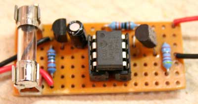
The prototype (see below) was built on strip board. The PIC uses an internal clock, so there are no particular concerns about trace length or layout.
The finished circuit was fitted into a pocket in the fursuit head.
The detailed operation is all contained within the the source code for the microcontroller. The program runs the internal clock at 4MHz, and uses Timer 1 to divide this down to a manageable 15kHz interrupt which is used to run the animation routines.
Timer 2 is configured in PWM mode at around 250Hz, and this is used to control the power to the LEDs. Using PWM allows for the fade effect to be easily handled.
A small table of cosine values is used to generate the eye fade. These values have been sort of corrected for the eye's non-linear perception of brightness. A pseudo random number generator is used to vary the period between blinks and choose the animation.
This is the unit fitted inside Zuki's head.
This circuit is provided as an application idea. I cannot accept any responsibility for use of this idea whether it is constructed correctly or not. I'd recommend thoroughly testing any constructed circuit before including it in a fursuit, and taking care to ensure the performer and the circuit cannot come to any harm in the event of an accident.
![]() This work is licenced under a
Creative Commons Licence.
I'd appreciate a quick
e-mail
or feedback if you have used or improved on the design.
This work is licenced under a
Creative Commons Licence.
I'd appreciate a quick
e-mail
or feedback if you have used or improved on the design.